Level sensor PMP-053 with «dry» contacts
Application
Level sensor PMP-053 is designed for monitoring of 1 … 2 levels of tank filling by means of switching of “dry” contact when the specified value of liquid level is reached.
Level sensor is designed for installation on the side wall of the tank and may be used in technological systems and aggregates for automatic control of the transporting pump or solenoid valve; prevention of tank overfilling, pump “idle” work and other applications.
Features
- simple application, commissioning and maintenance
- anti-vandal housing made of aluminum alloy or stainless steel
- various types of signal outputs
- explosion-proof modification
- transport modification for mobile tanks including naval and riverine vessels
- various types of mounting devices for protective cable sheath (metal hose conduit, armored cable, pipe)
Design, principle of operation
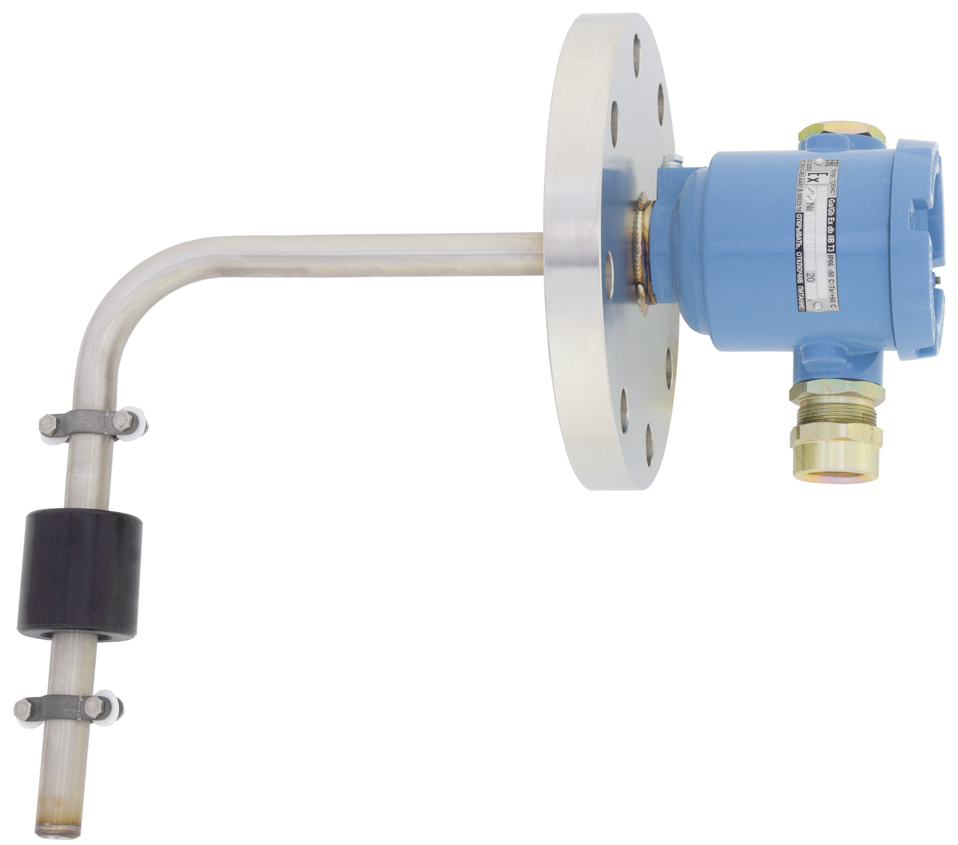
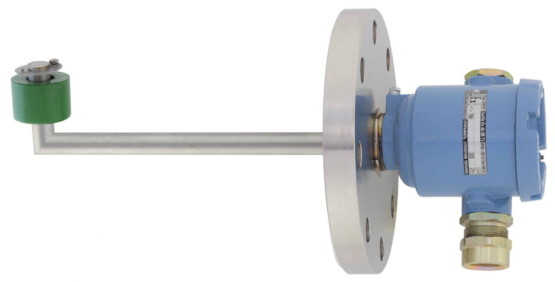
The PMP (see figure 1) consist of L-shaped guide pipe which is bended or welded of 2 pcs of pipe (steel 12Cr18Ni10Ti), which is welded to a steel cylinder-shape housing with a cable entry and threaded cover. There is one moving float on the guide, its moving progress is limite by stoppers. PMP is mounted to the side wall of then tank by means of the flange. A plate with screw terminals connected with magnetic reed relays (magnetic sensitive contacts) available in the guide piece is mounted in the case. For load-carrying capacity increase, as an option, PMP sensors may have electronic modules with the following output: transistor (DC24) or symistor (АС24, АС220). Modules do not require separate power.
Operation principle of PMP is based on application of reed switches within the guide pipe that change their state (closed / opened) when magnetic float impacts them.
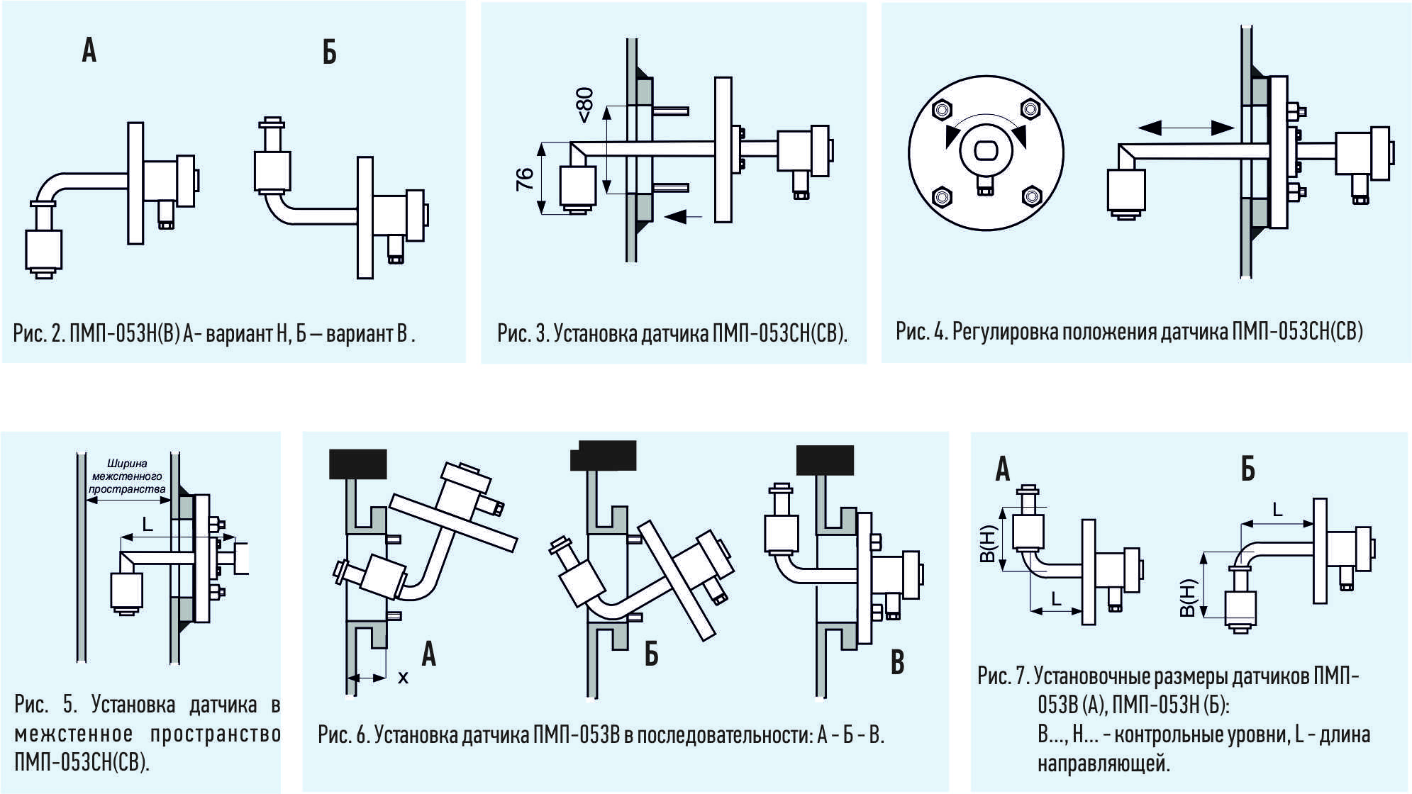
There are 4 modifications of sensor:
PMP-053N – guide pipe is a bended pipe (see fig. 2A), directed to the same side with the cable entry
PMP-053V – guide pipe is a bended pipe (see fig. 2B), directed to the opposite side from the cable entry
PMP-053SN – guide pipe is welded from two pipe segments (see fig. 1), directed to the same side with the cable entry
PMP-053SV – guide pipe is welded from two pipe segments, directed to the opposite side from the cable entry (modification with non-adjustable flange).
Modifications SN and SV variants have the following features:
1) small height of the vertical part of the guide pipe (76 mm) allows direct installation in the coupling flange, with internal diameter not less than 80 mm (see figure 3);
2) the use of the adjustable flange (default variant “2-80-25” as per GOST 12815-80) allows to move and rotate the guide pipe (see figure 4). It reduces requirements to position of holes in the mating
flange on the tank (the float must be in strict vertical position) and allows to install sensor float vertically or in the middle of interstitial space (see figure 5).
PMP-053N and PMP-053V modification has the following features:
1) flange and guide pipe are connected rigidly (welded), that’s why mating flange on the tank shall be strictly oriented so the float of the sensor is installed vertically;
2) sensor installation (see figure 6) is limited by height x of mating flange (pipe with flange). Maximal acceptable x value is determined by diameter of flange, installation dimensions L, H, B (see figure 7) and internal diameter of the flange (flange pipe).